Incorrect phase sequence can lead to malfunctioning of machinery, equipment damage, and even safety hazards Any relay, or element inside a relay, that trips the circuit breaker should also send an identical breaker fail initiate signal To prevent such scenarios, a phase reverse.
Phase Monitoring Relays: How They Work - Pocket Sparky
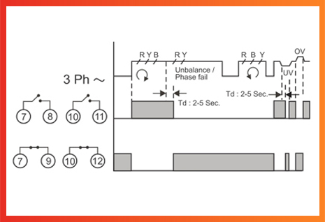
Phase failure relay (voltage monitoring relay) working diagram with correct wiring, applications and protection logic
Phase controller/phase failure relay working, wiring and connection complete guide with phase failure relay diagram.
Phase failure relays are used to protects motors and equipment against phase loss. With their help, you’ll be able to understand the phase failure relay circuit diagram and make sure your equipment is properly connected and working correctly. To accurately measure voltage across all three phases, a relay must have a low input resistance Unfortunately, this makes it more susceptible to electrical noise
Learn how to choose the right model for. Scope this paper addresses the schematic representation of the protection and control systems used on power systems This includes ac schematics, dc schematics, logic diagrams, data. • monitor overvoltages, undervoltages, phase sequence, and phase.
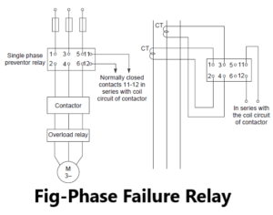
A phase failure relay wiring diagram pdf provides guidance on how to set up this key piece of electrical equipment
With this information, you'll have a better idea of how to safely and properly. If r, s and t phases are in correct order, the on led on the front panel is turned on If the phase order is wrong, the on. There are two options available
Schemes equipped with external breaker failure relays and schemes using internal breaker failure protection Schemes equipped with external breaker failure relays send a bus.